Getting Started
This section provides information on how to install the Cisco Nexus 3550-H Hydra (formerly ExaLINK Hydra).
Package contents
The Nexus 3550-H box should contain the following items:
- Nexus 3550-H box
- Nexus 3550-H Chassis
- Rackmount kit
- 8x M6 rack-mounting nuts
- 8x M6 rack-mounting bolts
- 8x M6 rack-mounting washers
- 2x IEC power leads
- 1x Serial port adapter cable
- 2x Mounting extension rails
Already installed should also be:
- 2x Power supply modules
- 3x Fan modules
Note: that the power supplies have an arrow on the exhaust fan that points in the direction of airflow. Fan modules are colored red for front-to-back (FTB, i.e. connector side intake) airflow and blue for back-to-front (BTF, i.e. connector side exhaust) airflow.
Mounting the Cisco Nexus 3550-H Hydra
Since the power supplies and fans add significant weight to the Nexus 3550-H, it is recommended that the system is rack mounted prior to installing them. Note: that two people are required to complete the installation.
- Clip the supplied-mounting nuts into the rack as shown, noting the gap of one notch between the nuts.
- One person should hold the Nexus 3550-H, aligning the front panel of the Nexus 3550-H with the nuts.
- The second person can then affix the washers and bolts to each of the four mounting holds on the front panel of the Nexus 3550-H, securely fastening them to the nuts.
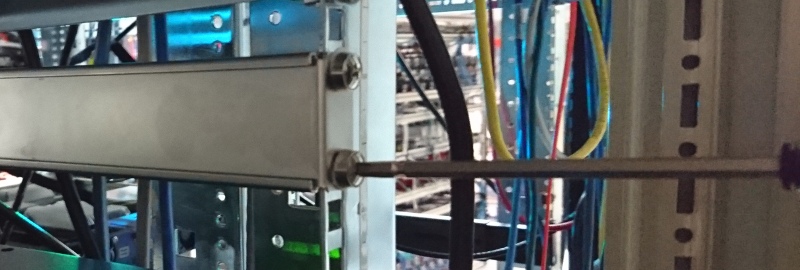
Mounting the Cisco Nexus 3550-H Hydra with rear support rails
The Nexus 3550-H ships with rear support rails. These can be added for extra structural support for the rack system. The process for installing these is as follows:
- Fasten the rear rails at the desired height.
Attaching the right hand side rail.
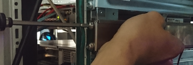
Attaching the left hand side rail.
- Lift the Nexus 3550-H to the desired height and align the installed rails with the rail mounting holes on the rear of the Nexus 3550-H.
- Slowly rack the Nexus 3550-H by sliding back onto the rails, until the front is flush with the rack.
- Fasten the Nexus 3550-H onto the rack as per the method for installing the front mount bolts. Due to the Nexus 3550-H's weight it may be easier with the aid of another person.
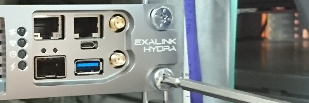
Fasten the Nexus 3550-H in the normal manner.
Installing Power Supplies
To install a power supply module:
- The power supply orientation is the same for both left and right supplies. Note the position of the IEC power input, which should be on the right when viewed from the rear.
- Push the power supply module in until a click is heard. The quick release lever should now be engaged.
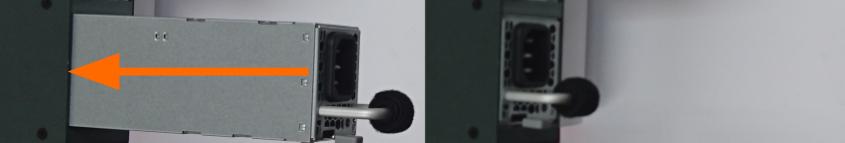
Installing a power supply
The Nexus 3550-H power supplies are redundant and failover from one to the other is automatic. It is recommended to operate the device with both power supplies installed, however, it will operate with only a single supply.
To remove a power supply module in the future simply press the quick release lever whilst pulling on the removal handle on the rear of the supply
Installing DC Power Supplies
Warning
Only trained and qualified personnel should be allowed to install, replace, or service this equipment.
Statement 1030
Note
You need to use your own 10 AWG copper wire and ring terminal. These are not included.
Warning
To reduce risk of electric shock, when installing or replacing the unit, the ground connection must always be made first and disconnected last.
Warning
To reduce risk of electric shock, before performing any of the following procedures, ensure that the DC power source circuit-breakers are in the OFF position.
Step 1: Using a wire-stripping tool, strip each of the three wires from the DC-input power source to the appropriate length for the terminals.
Warning
Use copper conductors only. Statement 1025
Step 2: Using a Panduit crimping tool, crimp the ring terminals to the copper conductor, 90C, 10-AWG DC power input wires.
Important
In Step 3, ensure the ground wire is connected first.
Step 3: Connect the DC-input power terminals to the terminal blocks. Make sure to match the polarity (negative to negative, positive to positive) when connecting the wires to the terminal blocks. Connect the ground wire to a grounded metal rack or to earth ground if the switch is not in a grounded rack.
Step 4: Torque all terminal block screws to 11 lbf-in.
Step 5: Move the DC power source circuit-breakers to the ON position.
Step 6: Confirm the LED on the power supply is solid green to indicate outputs are on and in regulation.
Installing Fan Modules
To install a fan module:
- Note: the position of the power connector on the fan module, relative to the power connector on the Nexus 3550-H. Rotate the fan module so that it aligns with the Nexus 3550-H connector.
- Push the fan module into the Nexus 3550-H until it is flush with the rear panel. The fan module will click into place when it is fully installed.
A fan module can be removed by pressing the release tab on the fan module.
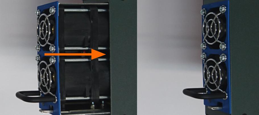
Installing a fan module
Installing cables and QSFP/QSFP-DD modules
Once power supplies and fans have been installed, it is possible to install the power supply cables, management interface cables and any QSFP cables/modules to the Nexus 3550-H. QSFPs must be inserted face down, such that the exposed contacts of the QSFP are towards the bottom of the connector.
QSFP-DD modules are only compatible with the Cisco Nexus 3550-H Hydra L1-160 (formerly ExaLINK Hydra 160), and not with the Cisco Nexus 3550-H Hydra L1-144 (formerly ExaLINK Hydra 144).
Both QSFP and QSFP-DD modules are supported on Nexus 3550-H L1-160 connectors. These will occupy 4 of the 8 available interfaces on a particular connector. These modules have a similar form factor, consult the images below for a guide on how to determine the difference between these modules.
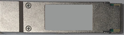
A QSFP module
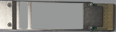
A QSFP-DD module. The -DD variant has longer teeth, which can be used to determine the difference between the two.
See Configuration for information on setting up the management interface of the Nexus 3550-H.
This page was last updated on Feb-18-2021.