Getting Started
This section provides information on how to install the Cisco Nexus 3550-F Fusion (formerly ExaLINK Fusion).
Package Contents
The Nexus 3550-F box should contain the following items:
- Nexus 3550-F box
- Nexus 3550-F Chassis
- Rackmount kit
- 8x M6 rack-mounting nuts
- 8x M6 rack-mounting bolts
- 8x M6 rack-mounting washers
- 2x IEC power leads
- 1x Serial port adapter cable
- 2x Mounting extension rails (units shipped after 2018)
Already installed should also be:
- 2x Power supply
- 2x Fan modules
Note
The power supplies have an arrow on the exhaust fan that points in the direction of airflow. Fan modules are colored red for front-to-back (FTB, i.e. port side intake) airflow and blue for back-to-front (BTF, i.e. port side exhaust) airflow.
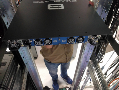
Mounting the Cisco Nexus 3550-F
Since the power supplies and fans add significant weight to the Nexus 3550-F, it is recommended that the system is rack mounted prior to installing them.
Note
Two people are required to complete the installation.
- Clip the supplied-mounting nuts into the rack as shown, noting the gap of one notch between the nuts.
- One person should hold the Nexus 3550-F, aligning the front panel of the Nexus 3550-F with the nuts.
- The second person can then affix the washers and bolts to each of the four mounting holds on the front panel of the Nexus 3550-F, securely fastening them to the nuts.
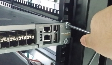
Mounting the Nexus 3550-F into a rack
Mounting the Cisco Nexus 3550-F With Rear Support Rails (Units Shipped After 2018)
The Nexus 3550-F ships with rear support rails. These can be added for extra structural support for the rack system. The process for installing these is as follows:
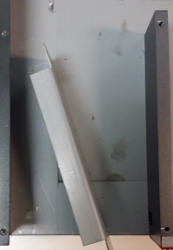
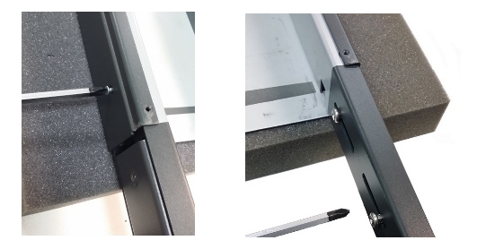
- Fasten the rear rails at the desired height. Ensuring that the indicator arrow on the flange is pointing upwards.
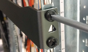
Attaching the right hand side rail.
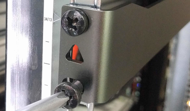
Attaching the left hand side rail.
Example of attached left hand side rail.
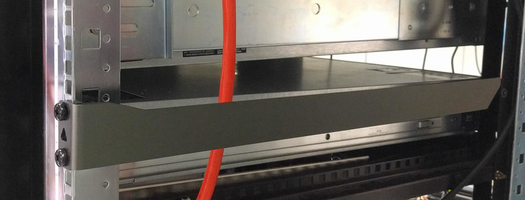
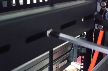
- Lift the Nexus 3550-F to the desired height and align the installed rails with the rail mating wholes on the rear of the Nexus 3550-F.
Inserting the right hand side rail.
Inserting the left hand side rail.
- Slowly rack the Nexus 3550-F by sliding back onto the rails, until the front is flush with the rack.
Sliding back on both rails.
- Fasten the Nexus 3550-F onto the rack as per the method for installing the front mount bolts. Due to the weight of Nexus 3550-F, it may be easier with the aid of another person.
Fasten the Nexus 3550-F in the normal manner.
Mounting the Cisco Nexus 3550-F With Rear Supports (Units Shipped Before 2019)
The Nexus 3550-F ships with rear support mounting brackets. These can be added for extra structural support for the rack system. The process for installing these is as follows:
- Remove both of the power supplies from the Nexus 3550-F (see above).
- Remove both screws from each of the rear mount bars to separate the mounts into their constituent pieces.
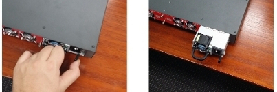
- Locate, unscrew and remove the brackets in the rear of the Nexus 3550-F (pictured below).
Removing the rear brackets of the Nexus 3550-F (screw locations also pictured).
- Replace the power supplies.
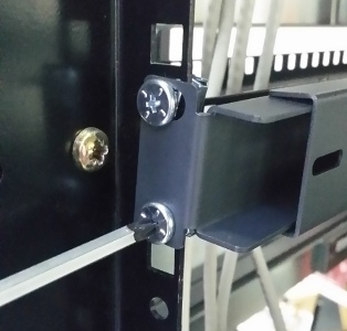
- Fasten the rear mounts to where the removed brackets were previously. Ensure that the flaps for the bolts are facing outwards (i.e. in line with the front mount positions).
Attaching the rear mounts of the Nexus 3550-F, with inserted power supplies.
- Mount the Nexus 3550-F onto the rack as per the method for installing the front mount bolts. Due to the weight of Nexus 3550-F, weight it may be easier with the aid of another person.
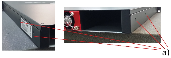
- Remove the two screws restricting the rear mounting extension and adjust it so it fits the required depth for the mounting solution (Pictured below). When in place, apply the rack mount brackets and bolts.
Rear mounts being screwed into place.
- Replace the two screws for the rear mounting extension to lock the Nexus 3550-F in place.
Variable length sections being secured in.
Note: It is also acceptable to reinsert the power supplies after the Nexus 3550-F has been successfully mounted into the rack to reduce the weight during rack mounting.
Installing Power Supplies and Fans
The power supplies and fans can now be installed into the Nexus 3550-F chassis.
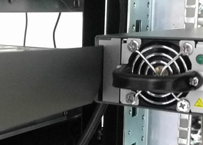
To install a fan module:
- Note the position of the power connector on the fan module, relative to the power connector on the Nexus 3550-F. Rotate the fan module so that it aligns with the Nexus 3550-F connector.
- Push the fan module into the Nexus 3550-F until it is flush with the rear panel.
- Tighten the two screws to lock the fan module into position.
A fan module can be removed in the future by loosening the screws and pulling out the module.
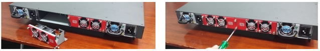
Installing a fan module
To install a power supply module:
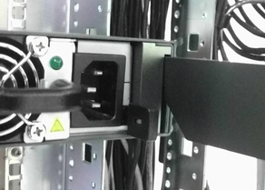
- The power supply orientation is the same for both left and right supplies. Note the position of the IEC power input, which should be on the right when viewed from the rear.
- Push the power supply module in until a click is heard. The quick release lever should engage at this point.
Installing a power supply. Note the position of the IEC connector and the use of the quick release lever (left image).
The Nexus 3550-F power supplies are redundant and failover from one to the other is automatic. It is recommended to operate the device with both power supplies installed, however, it will operate with only a single supply.
To remove a power supply module in the future simply press the quick release lever whilst pulling on the removal handle on the rear of the supply
Installing Line Cards
Line cards are installed into the front of the Nexus 3550-F. Your Nexus 3550-F will arrive with line cards pre-installed as per your order, however if you wish to install additional line cards in the future, the following steps are required.
- Ensure the Nexus 3550-F is powered down. Hot-plugging of line cards will not damage the device, but currently the software will not recognize additional line cards until a power cycle.
- Take the line card and align the edges with the card-guides in the line card bay.
- Push the line card in. The front panel door will swing upwards and out of the way. The line card will engage the connector at the rear of the bay, and a noticeable increase in force will result.
- Push until the line card is flush with the front panel.
The bottom bracket on the line card doubles as an ejection lever. To eject the line card:
- Apply force with a thumb to the 'ejection' symbol on the line card bracket. The lever should swing out at the opposite end.
- Pull on the lever. A cam mechanism will extract the line card from its connector.
- Once the connector force has been overcome, the line card should easily slide out of the line card bay.
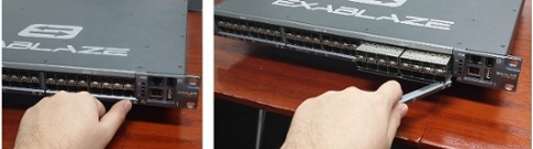
Removing a line card. Note the use of the ejection mechanism.
Installing Cables and SFPs
Once power supplies, fans and line cards have been installed, it is possible to install the power supply cables, management interface cables and any SFP or passive twinax cables to the Nexus 3550-F.
See Configuration for information on setting up the management interface of the Nexus 3550-F.
This page was last updated on Mar-08-2021.